Aim: Achieving Quantum Advantage
Why quantum advantage is not achieved in Demo(1)
Let’s focus on one neural computation. In Demo(1), the weights are directly encoded to quantum circuit. Assume there are N input neurons, corresponding to M=logN qbits, where N=16, M=4 in Demo(1). Demo(1) use (C^P)Z gate, P=M-1, for encoding weights. We can convert (C^P)Z gate to basic gates (e.g., X, CX, CCX) that can be completed in 1 cycle. The Gates and latency/cost related to M is listed as follow.
| P | Gate | Lat/Cost |
|---|---|---|
| 0 | Z | 1 |
| 1 | CZ | 1 |
| 2 | CCX+CZ+CCX | 3 |
| 3 | 2CCX+CZ+2CCX | 5 |
| 4 | 3 CCX+CZ+3 CCX | 7 |
| K | … | 2*K-1 |
| K | … | O(K) |
For the approach in Demo(1), in worst case, M qbits will need 2^M/2 = N/2 gates (see quirk example for 4 qbits with 15 (C^4)Z gates and the cost/time complexity of each gate is O(K), where K=M. So, the total time complexity is O(NM)=O(NlogN). In classical computer, the number of cycles is also O(N). Therefore, no quantum advantages are achieved at all.
How to achieve quantum advantage for Machine Learning?
The answer is to reduce/decompose (C^P)Z gates.
Basic Knowledge
The circuit is to encode the weights to make sure the sign of each amplitude is exactly the same with the weights.
Let’s go back to see the amplitude in Demo(1) as follows.
Neural 1:
[1.,  1.,  1.,  1.,  1.,  1.,  1., -1.,  1., -1.,  1., -1.,  1.,  1.,    1.,  1.]
Let’s show the operations to be conducted in quantum circuit as follow.
| Input | weight | |||||||
|---|---|---|---|---|---|---|---|---|
| A0000 | A0001 | A0010 | A0011 | 1 | 1 | 1 | 1 | |
| A0100 | A0101 | A0110 | A0111 | * | 1 | 1 | 1 | -1 |
| A1000 | A1001 | A1010 | A1011 | 1 | -1 | 1 | -1 | |
| A1100 | A1101 | A1110 | A1111 | 1 | 1 | 1 | 1 |
How can we do sign flip? (I just list the intuition here, fundamentals are matrix multiplication)
For example, the weight corresponding to A1001 is -1. To make its sign flip, we need a (C)(NC)(NC)Z gate. The basic ides is that for 1, it corresponds to Z or C (dots), and for 0, it corresponds to NC/NZ (circles).
If we only apply a Z gate on the last qbit, all related amplitude will be flipped, including A0001, A0011, A0101, A0111, A1001, A1011, A1101, A1111.
The trick we can take is that we can continuously flip different bits and make sure the final sign of each amplitude are exactly the same with that in weights.
What can we do for ML models?
The property that we use is that the inputs can be reordered, and in turn, the weight can be reordered.
Therefore, we do not need to care about the position of negative number in weights, but we do care about how many weights are -1, denoted as TN.
Let’s use notation “ZZIIZ” to represent that we place a CCZ gate on qbits 0,1,4, and all amplitude corresponding to 11XX1 will flip sign. We figure out the following table to show how many amplitudes are associate with one type of
gate. (using 4 qbits system as an example)
| Gate | Amplitude (A) |
|---|---|
| IIIZ | 8 |
| IIZZ | 4 |
| IZZZ | 2 |
| ZZZZ | 1 |
There are 16 amplitude in total. However, as we know, the quantum has symmetric property. Therefore, we only need to cover sign flip of 8 amplitude. We observe that we can use the gates listed in the table to achieve any number (<=8) of sign flip.
Case 1: TN = 8, 4, 2, or 1
In this case, we directly apply the corresponding gates.
Case 2: TN != 8, 4, 2, or 1
If we apply the above gate set in sequence, it has a property:
for the odd time, we will add A negative sign, for even time, we will remove A negative sign.
E.G., TN=5
It indicates that we need 5 negative sign; following the above property, we can have 8-4+1 = 5. We have a algorithm to help identify the order to gates used to achieve any number of negtaive signs. Details please see our paper.
Analysis.
The above algorihtm indicates that for M qbits, we will involve M gates at most. According to the first table in this Demo, the cost is 1+1+3+5+…+[2(M-1)-1]=1+[1+3+5+7+…+(2M-1)]-(2M-1)=M^2-2*M+2=O(M^2).
We know that the classical computer needs O(N)=O(2^M) adder/multiplier, but we only need O(M^2) quantum basic gates. Therefore, we achieve the quantum advantage.
QuantumFlow Results
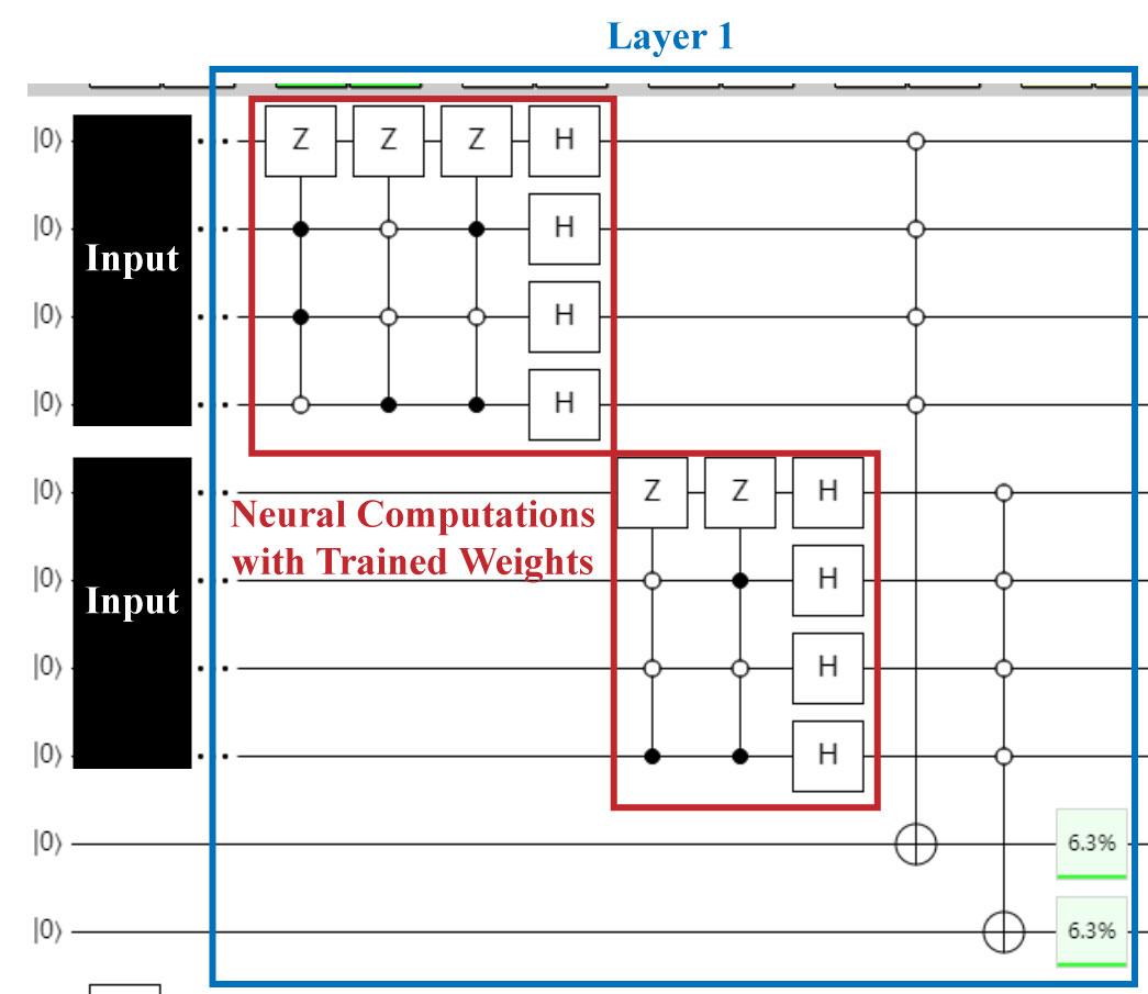
QF-Map
The algorithm to generate quantum circuit is implemented in QF-Map. The optimized quantum circuit is shown as follows, which has the same function as Demo(1), except the order of the inputs need to be changed.
We made examples in quirk, which can be accessed using the following links:
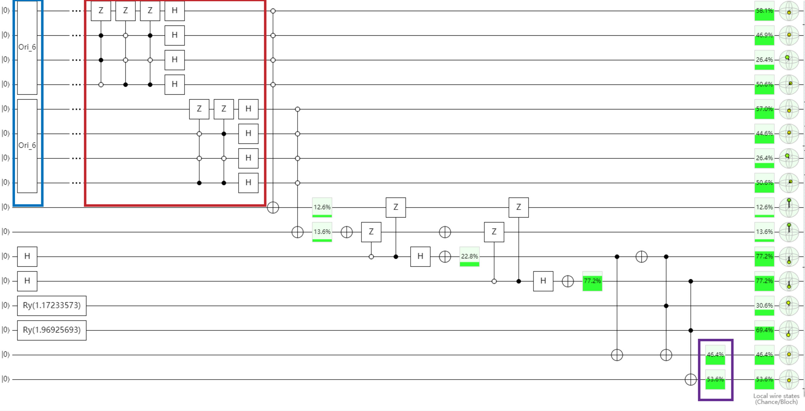
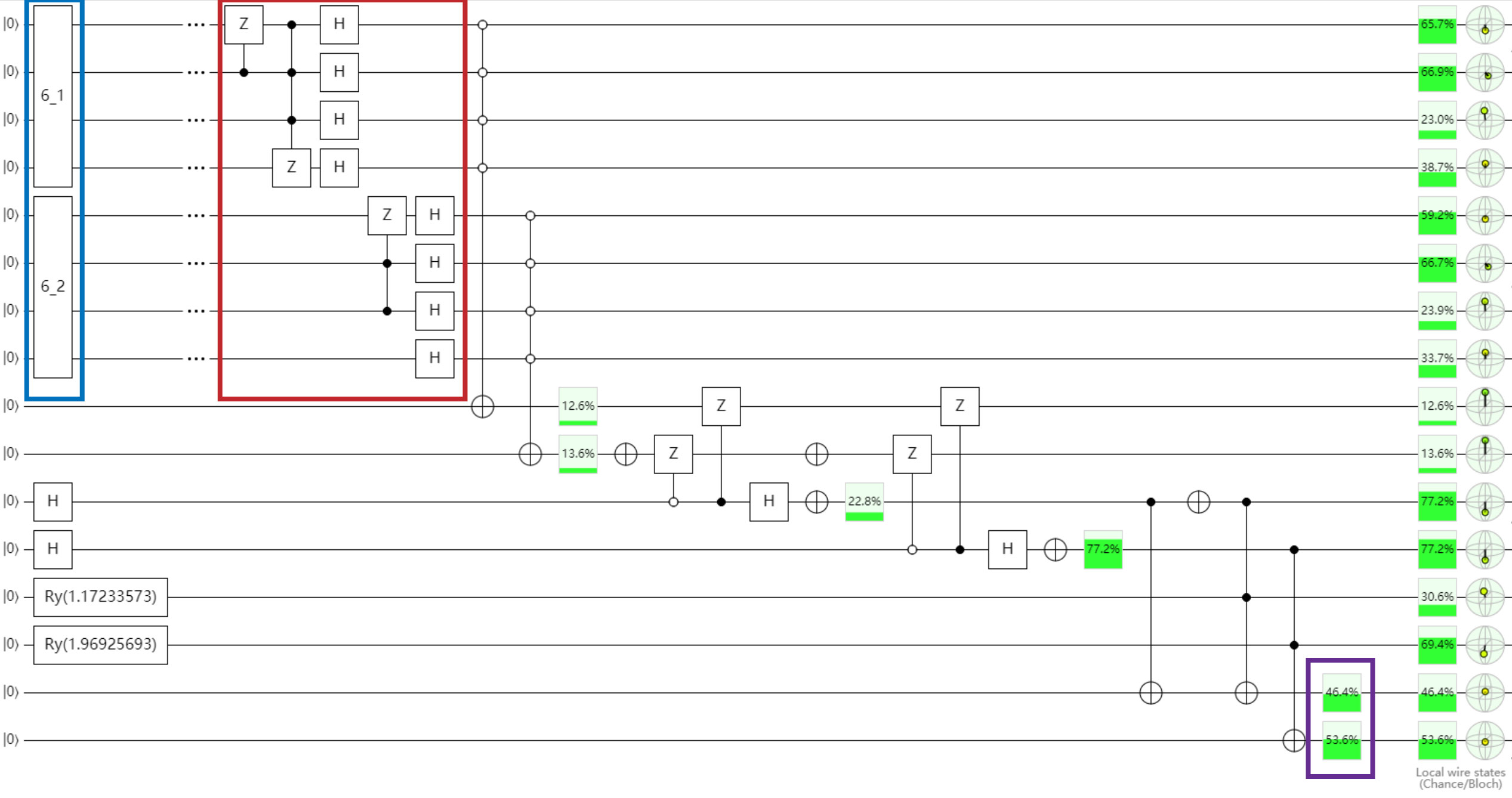
Optimized Circuit with the Same Results
Codes will be released to github soon.
